It is no secret that one of the key issues in aircraft engine building is the choice of bearing units. Depending on the type, such units receive the radial load, hold the weight of the rotor, and face axial forces due to the action of the flow path and the secondary flow’s static pressures. Rolling bearings are commonly used in aircraft engines.

To ensure their uninterrupted operation in hard conditions and different modes of friction with contacting parts, it is necessary to provide bearings with proper lubrication on the one hand, and adequate heat removal on the other. Heat generates because the power consumed to drive bearings is almost entirely converted into a heat flow. Furthermore, in aircraft gas turbine engines, hot engine parts–like the combustion chamber and turbine–also heat the bearings.
Oil Systems and Components.
In aircraft engines, a closed circulation lubrication system is widely used. One exception to this trend can be found in single-acting engines, where the system may be open and non-circulating. In such systems, fuel can be used as a lubricant.
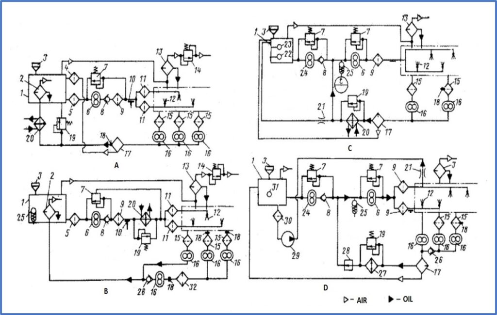
A typical oil supply system includes the following components: oil tank, supply pump, pressure reducing valves, filters, oil lines, scavenge pumps, de-oilers, and heat exchangers. From the oil tank, the oil is pumped through the supply pump and oil pipes, pre-cleaned through filters, and fed to the bearing using special channels or nozzles. In the process of interaction with the bearing, air is sucked into the oil, which forms an oil-air mixture. Once in the de-oiler, the air is separated from the oil by centrifugal forces and passes through the scavenge filters for purification. The purified oil enters the heat exchanger. There, the oil can be cooled by air or fuel. Fuel cooling is common in engines that operate in supersonic modes, since the high air stagnation temperature makes the use of air cooling untenable.

There are various schemes for the layout of circulating oil systems. The most common is a single-circuit scheme with a heat exchanger in the scavenge line (type A), or with a heat exchanger in the supply line (type B). Single-circuit systems are often used when the oil tank capacity is low. In addition to single-circuit schemes, there are two-circuit ones (type C) and short-circuit ones (type D). The use of single-circuit systems becomes difficult in engines with a long operation time, and in high-power turbojet and turboprop engines. In such cases, two-circuit schemes are used. These allow the oil to move according to the “engine-heat exchanger-engine” scheme, and only a small portion of the oil (10–20%) returns to the tank. Short-circuit systems are similar to two-circuit systems, and have become widespread in turboprop engines.
Design Challenges
Designing a new lubrication system for an engine typically requires overcoming complex and project-specific challenges. Selection of oil type with suitable viscosity is the first step. The next steps are to determine the required oil supply for effective cooling and lubrication, and engine layout arrangement. Ensuring the uninterrupted operation of the oil system in all operating modes of GTE requires consideration of all system components. This task calls for a comprehensive solution that accounts for the intake of oil from the tank with appropriate boundary conditions, the availability of established pump characteristics for all operating modes, and hydraulic resistance through the oil supply channels. An important factor is the selection and verification of bearing assembly seals, which should ensure the minimum possible oil leakage into the engine’s secondary air-cooling system. Correct calculation of heat generation is one of the key tasks. The oil supply will depend on how much heat needs to be removed. Heat generation is also impaired by air entering the oil. The analysis of heat transfer coefficients between the bearing wall and the oil-air mixture requires use of 3D CFD simulation to complete. However, CFD is traditionally resource-intensive and time-consuming.
Thermal-Fluid Network for GTE Lubrication
The working regime’s verification of the whole system, as well as the non-stationary calculation of critically important transient processes, can be effectively addressed using a thermal-hydraulic network. The approach is implemented in the AxSTREAM NET™ software, which can be used for analyzing GTE lubrication systems. When the lubrication system acts in synergy with the fuel system, heat exchange between hot oil and cold fuel both cools the oil and preheats the fuel before combustion.

Each oil/fuel pipe can be discretized at different levels of abstraction, in order to obtain an accurate distribution of results through the fluid network. Desired temperatures cannot be reached unless the thermal task in the heat exchanger is highly precise. To achieve this, heat exchanger fluid and surface paths can be modeled in detail and added to the entire scheme for analysis. The heat transfer coefficients can be calculated automatically according to the appropriate correlations for each task.

Even transient behavior, such as abrupt changes in engine operation modes, can be handled to prevent bearings from overheating. Check out this paper presented at Turbo Expo 2022 for more information.
In Summary
Lubrication system design and analysis are very important tasks which involve a number of complex iterations in steady-state and transient conditions. The arrangement of the system depends on engine type, its purpose, size, working regimes, the influence of radial and axial loads on the system and the load order, bearings selection, lubricant, thermal management, design of geometry arrangements and equipment selection, and analysis of fluid dynamics and heat transfer processes in the system. To cover all these different tasks, a 1D thermal-fluid network modeling approach can provide the necessary calculation accuracy while decreasing the time spent exploring design iterations under different conditions.
If you would like to learn more about the capabilities of AxSTREAM NET, get in touch by emailing us at Sales@Softinway.com
- SEO Powered Content & PR Distribution. Get Amplified Today.
- Platoblockchain. Web3 Metaverse Intelligence. Knowledge Amplified. Access Here.
- Source: https://blog.softinway.com/aircraft-engine-oil-supply-systems/
- 1
- 2022
- 3d
- a
- About
- According
- Accounts
- accuracy
- accurate
- Achieve
- Action
- acts
- added
- addition
- AIR
- aircraft
- All
- analysis
- analyzing
- and
- approach
- appropriate
- arrangement
- Assembly
- automatically
- availability
- because
- become
- becomes
- before
- between
- Building
- calculated
- Calls
- cannot
- capabilities
- Capacity
- cases
- CFD
- challenges
- Chamber
- Changes
- channels
- characteristics
- check
- choice
- circulating
- Circulation
- closed
- COM
- commercial
- Common
- commonly
- complete
- complex
- components
- comprehensive
- conditions
- consideration
- consumed
- converted
- cover
- Depending
- depends
- Design
- detail
- Determine
- different
- difficult
- distribution
- drive
- dynamics
- each
- Effective
- effectively
- Engine
- Engines
- ensure
- ensuring
- Enters
- Entire
- entirely
- equipment
- established
- exception
- exchange
- exchangers
- Exploring
- Expo
- Face
- Fed
- Figure
- filters
- First
- flow
- Fluid dynamics
- following
- Forces
- forms
- found
- friction
- from
- Fuel
- Furthermore
- GAS
- generates
- generation
- get
- Hard
- High
- highly
- hold
- HOT
- How
- However
- HTTPS
- implemented
- important
- in
- includes
- influence
- information
- interaction
- involve
- issues
- IT
- iterations
- Key
- Layout
- LEARN
- levels
- Line
- lines
- load
- loads
- Long
- Low
- MAKES
- management
- max-width
- minimum
- mixture
- more
- Moscow
- most
- move
- necessary
- needs
- net
- network
- New
- next
- number
- Oil
- ONE
- open
- operate
- operating
- operation
- order
- Other
- part
- parts
- passes
- path
- pipe
- plato
- Plato Data Intelligence
- PlatoData
- possible
- power
- presented
- pressure
- prevent
- process
- processes
- proper
- provide
- pump
- pumps
- purpose
- reached
- receive
- reducing
- removal
- Removed
- required
- requires
- Resistance
- resource-intensive
- Results
- returns
- Rolling
- scheme
- schemes
- secondary
- Secret
- selection
- should
- similar
- simulation
- since
- Size
- small
- Software
- solution
- special
- spent
- STAGNATION
- Step
- Steps
- such
- suitable
- supersonic
- supply
- Surface
- synergy
- system
- Systems
- Task
- tasks
- The
- their
- thermal
- Through
- time
- time-consuming
- to
- touch
- traditionally
- transfer
- Trend
- typical
- typically
- under
- units
- us
- use
- various
- Verification
- weight
- which
- while
- widely
- widespread
- will
- working
- would
- zephyrnet


