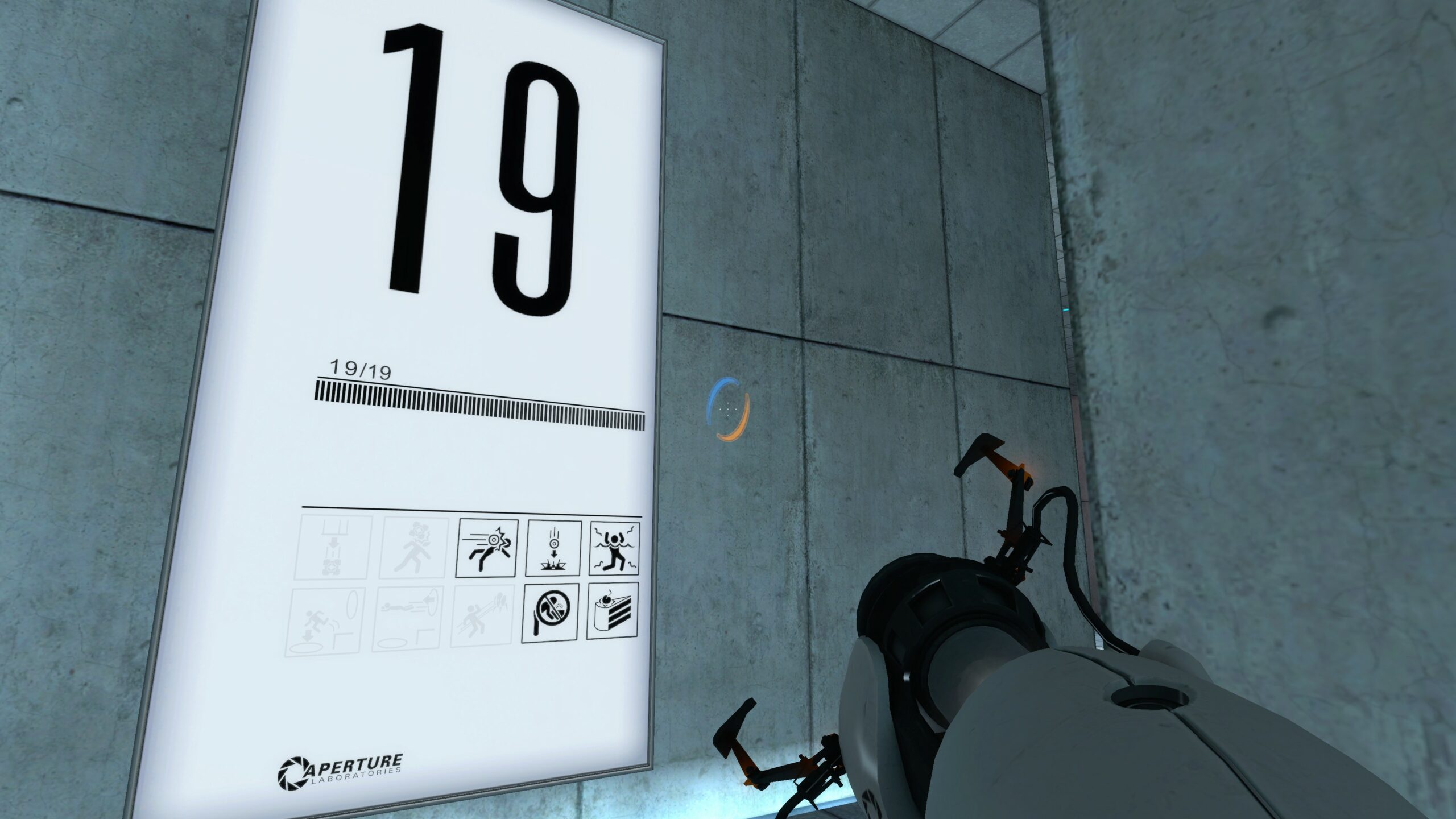
Last year, I found myself compelled to make a scaled-down replica of the iconic test chamber signs from the video game Portal. If you’ve played the game, you’ll remember these signs as the illuminated monoliths that postmarked the start of every test chamber. In hyperstylized video game fashion, they were also extremely thin.

True to the original, my replica would need to be both slimmed down and backlit with a uniform, natural white glow. As fate would have it, the crux of this project was finding a way to do just that: to diffuse light coming in from the edges so that it would emit evenly from the front.
What I thought would be quick project ended up being a dive down the rabbit hole that yielded some satisfying results. Today, I’d like to share my findings and introduce you to light guide plates, one of the key building blocks inside of much of today’s backlit screen technology. I’ll dig into the some of the working principles, introduce you to my homebrew approach, and leave you with some inspirational source code to go forth and build your own.
Hobby and Industry Practices
Tackling this project made me wonder: how do manufacturers in the electronics industry illuminate those ultra-flat laptop displays and TV screens to get a perfectly uniform glow? Following a bit of internet research, I discovered a treasure trove of useful insights.
Before we dive too deep into how the consumer electronics industry solves this problem, I want to first walk you through an analogous hacker side-project: the laser-cut acrylic edge-lit display. We’ve featured quite a few projects like these on Hackaday, and they’re just the right level of complexity to get your feet wet at the local Hackerspace.
The core concept is that clear acrylic sheets have the ability to act as fiber optics, piping light from one edge to the other. The journey isn’t perfectly straight though. Much of the light enters at an angle, bouncing back and forth between top-and-bottom surfaces before exiting the other edge. By etching a pattern on one surface of the acrylic, we create a location where the light is absorbed and emitted, rather than mostly reflected. We can take advantage of this quirk to create some pretty swanky looking signage.
Something that careful observers might point out: image features that are further away from the light source are noticeably dimmer. To understand that phenomenon, we need a bit of physics.
Some Background Theory: Snell’s Law
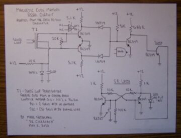
Some fairly simple optics theory behind this hacker project can help us understand what’s going on. Let’s start with a cutaway side view of this project where the left side is illuminated by a bar of LEDs.
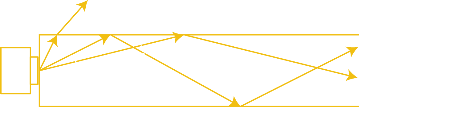
In this setup, a light source shines from one edge of the plate, sending light rays into the plate at a range of angles. It turns out that there exists special angle Φc called the critical angle. Light rays hitting the surface boundary at less than Φc will exit the plate immediately at a slightly different exit angle according to Snell’s law. Light rays hitting the surface at angles greater than or equal to Φc will be totally internally reflected. In other words, they will continue to bounce around inside the plate at a fixed angle forever, unless they are interrupted. For glass and plastic, Φc ≈ 42°.
By etching the surface of the plate, we create locations where the internally reflected light rays can scatter and exit the plate at a specific location, rather than reflect back internally. This is the phenomenon that causes the signs to glow.
At this point you might be able to guess why etched features of the sign become dimmer as they get further from the light source. It’s because a larger portion of the internally reflected light rays have already exited the plate earlier on.
Industry Practices
It turns out that LCD manufacturers implement a backlighting scheme that uses a similar approach to what we’ve seen so far. Peel back the inside of a liquid crystal display to find that it actually consists of a sandwich of many layers. Separate those layers to find a polarizing layer, a liquid crystal layer, a diffuser layer, clear fiber optic sheet, and finally a thin reflective backing layer. This thin fiber optic sheet, called a light guide plate, is illuminated from the screen edge with a bar of LEDs. The goal of this plate is to take internally reflected light from the edge and release it in a controlled fashion along the surface such that the front of the screen is evenly lit.

Similar to the sign projects from above, manufacturers mark the surface of the sheet with a pattern of dots, creating escape points for the light to exit along the way. The diffuser layer takes the illuminated light from this pattern and diffuses it further into a uniform light source, and the reflective layer prevents the light from escaping prematurely out the wrong side.
Beyond these basics, though, is where manufacturers start to differ in their own tweaks to this recipe. First off, light guide plates can be made from either acrylic or polycarbonate. They can be either flat or slightly “wedge-shaped,” where the angle of the wedge helps distribute the light more evenly. They can be marked by laser (acrylic only) or by injection mold where the mold actually carries small detents to transfer the pattern. Finally, the dot pattern can vary in density according to a polynomial or exponential function.
From my background reading, I was pleasantly surprised that plenty of vendors will also sell you a host of items relevant to making displays. Reach out to 3M, and you’ll likely hear back with a host of polarizers and “brightness-enhancement” sheets all intended for this purpose. Dig through Aliexpress, and you’ll find vendors offering you a range of “backlight bars” of component LEDs made to replace those found in laptop and tv screens. Dig deeper, and you’ll even find vendors offering made-to-order acrylic panels with a diffuser grid pattern etched onto them, although the pattern options are somewhat limited.
The Homebrew Light Guide Plate Approach
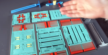
Inspired by my reading, I started with a first-draft making my own sandwich for my Portal sign. While it turns out that you can buy many of the real materials that go into actual LCD panels by 3M, they come at a hefty pricetag in low quantities, so I settled for some cheaper reflective substitutes. My final stack consisted of:
- PET overhead transparency with the Portal sign replica printed on the surface
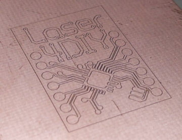
- 3 mm opaque white cast acrylic, laser-cut to size
- 3 mm clear cast acrylic, laser-cut to size and etched with a diffuser pattern
- Solar Window Tint Film from Tap Plastics
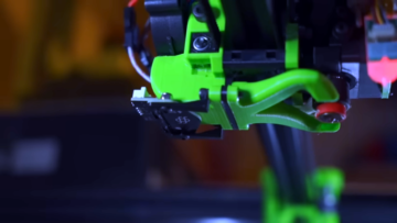
The stars really aligned well for this project to be something anyone with a CO2 laser cutter nearby can tackle. First, most of the raw materials are either readily available, or cheaper substitutes exist. Second, by nature of these panels being laser cut, the panel edge gets a nice flame polish in the process of being made. This is critical to increase the amount of light entering the panel. Overall, I was thrilled to be doing most of the fabrication in the home workshop.
Quick and Dirty First Drafts
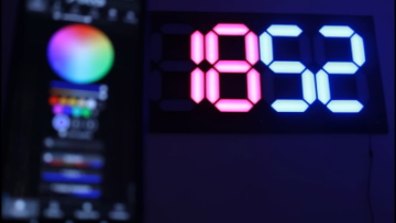
To find out how much effort I’d need to put into makinig an even backlight, I started with something simple. I started by making an evenly-spaced grid etched on the surface of the clear acrylic, covered the bottom with the window tint film, and illuminated it from two sides with two LED backlight bars. As a quick test, I covered the panel with the opaque white sheet and observed it from a distance.
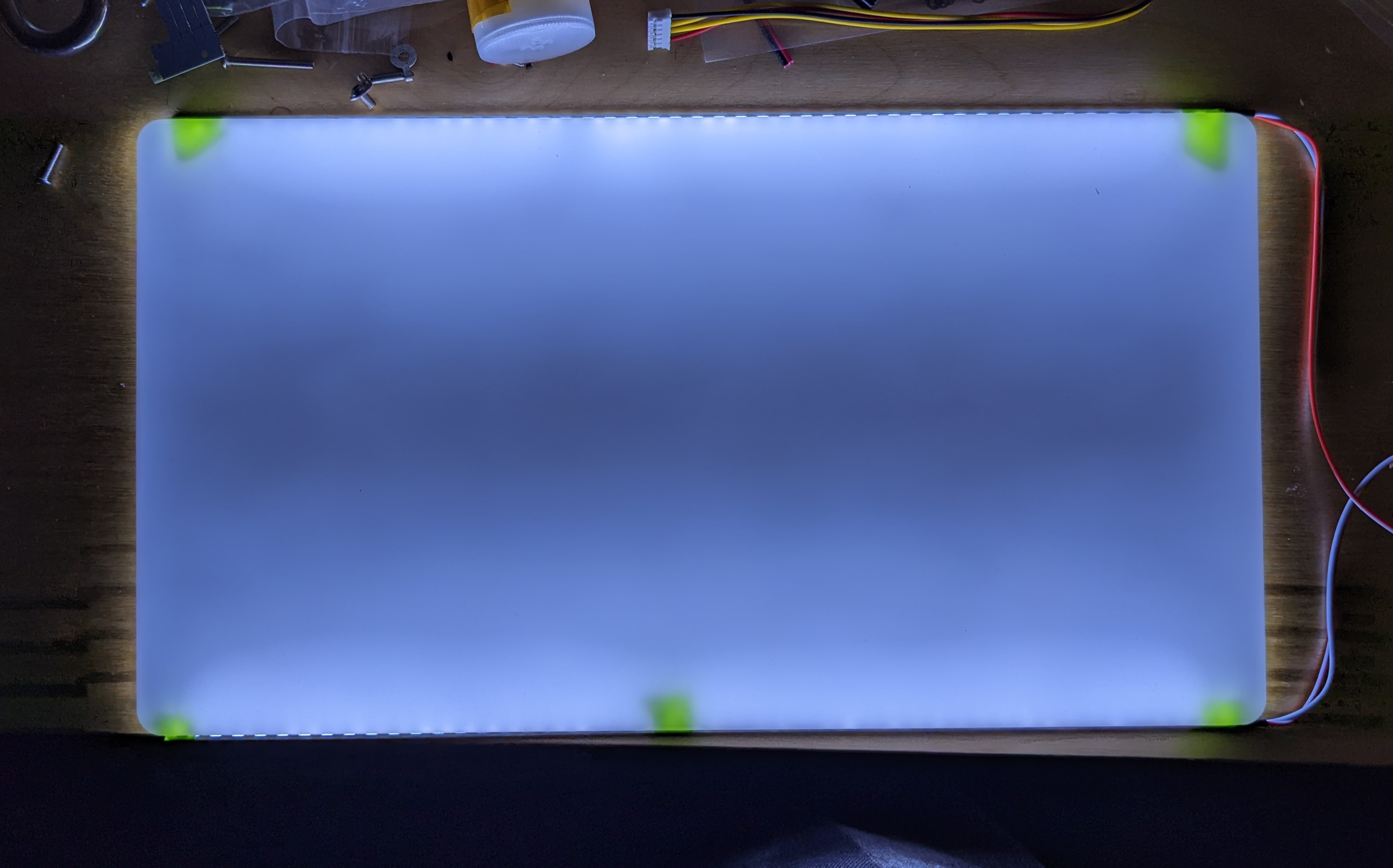
Unfortunately, the results weren’t convincing, but I learned plenty from this setup.
It was clear that the stackup was noticeably dimmer in the middle, the furthest point from the light sources, and the effect was even worse on camera. After another trial, I also noticed that there was an upper limit on how far apart I could space the pattern elements before they started appearing through the diffuser as discrete light sources. I was hoping to avoid writing some custom software to generate the panel pattern, but here we go.
Diffusing Light–Now with BSplines
At this point, I realized that I needed some finer control on these laser parameters, so I cooked up a Python notebook to generate a panel of specified XY dimensions with a custom dot pattern and write the result to an SVG file. For tuning knobs, I wanted to be able to manipulate dot density as a function of distance from the light source. To do so, I created an interactive 2D graph where I could drag around 5 points, and fit them to a second order B-Spline. The result looked like so:
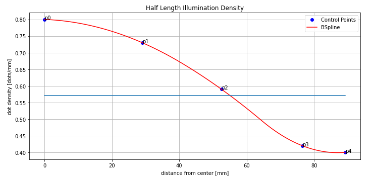
This script I wrote had some nice constraints on it. First, I could enforce a maximum dot spacing so that the script would never generate a pattern that was so sparse that it would appear as discrete light sources. Next, I could mirror the results to apply the pattern to a panel illuminated from two sides. Finally, I could actually record the parameters of my test pieces.
Armed with some new software tooling, I started generating squatty light guide plate samples, illuminating them from both sides under the diffuser, and checking the results. After about 6 tries, I had something good enough to fool me–and my camera!
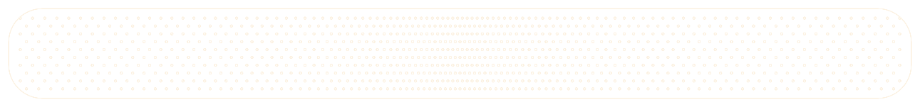
Feeling comfortable with my settings, I cut a full size piece and assembled my final light plate sandwich.
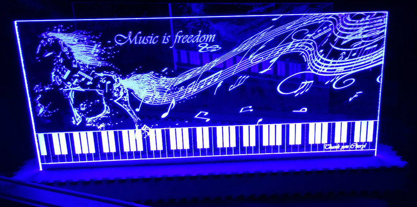
And, without further ado: the final results after assembly.
It’s not 100% perfect, but it’s more-than-convincing for both my eyes and for smartphone cameras. It’s also light years ahead of my original naive approach.
As far as software goes, there are plenty of usability improvements worth adding. It would also be a worthy exercise to try to derive the density curve from a calibration image, a flat field correction of sorts. But I’ll leave those items as an exercise for the reader.
We do what we must. because. we can.
This is one of those projects that I was hoping someone had already written up so that I could adopt their results (and credit them, of course!) and use them in my project. In this case, I had to roll up my sleeves and be that someone. But I’m happy to report back with the fruits of my labor. If you’re curious enough to follow this rabbit hole, you are most welcome to have a go at my crude light guide plate generator notebook. Who knows? Maybe in the future, this sort of feature will get integrated into other laser software packages if we ask nicely.
References
- SEO Powered Content & PR Distribution. Get Amplified Today.
- Platoblockchain. Web3 Metaverse Intelligence. Knowledge Amplified. Access Here.
- Source: https://hackaday.com/2023/03/13/a-hackers-introduction-to-diy-light-guide-plates/
- :is
- $UP
- 1
- 2D
- 5G
- 7
- 70
- a
- ability
- Able
- About
- above
- According
- Act
- actually
- adopt
- ADvantage
- After
- ahead
- aligned
- All
- already
- Although
- amount
- and
- Another
- anyone
- apart
- appear
- Apply
- approach
- ARE
- around
- article
- AS
- assembled
- Assembly
- At
- available
- avoid
- back
- background
- backing
- bar
- bars
- Basics
- BE
- because
- become
- before
- behind
- being
- between
- Bit
- Blocks
- Both Sides
- Bottom
- Bounce
- build
- Building
- buy
- by
- CAKE
- called
- camera
- cameras
- CAN
- careful
- case
- causes
- Chamber
- cheaper
- checking
- class
- clear
- co2
- code
- come
- comfortable
- coming
- compelled
- complexity
- component
- concept
- constraints
- consumer
- Consumer electronics
- continue
- control
- controlled
- cooked
- Core
- could
- covered
- create
- created
- Creating
- credit
- critical
- crude
- Crystal
- curious
- curve
- custom
- Cut
- deep
- deeper
- density
- Derived
- differ
- different
- DIG
- dimensions
- discovered
- Display
- displays
- distance
- distribute
- Diy
- doing
- DOT
- down
- dramatically
- Earlier
- Edge
- effect
- effort
- either
- Electronics
- elements
- enough
- Enters
- EOS
- Ether (ETH)
- Even
- Every
- Exercise
- exists
- Exit
- Exiting
- exponential
- extremely
- Eyes
- fairly
- Falls
- far
- Fashion
- Feature
- featured
- Features
- Feet
- few
- field
- File
- Film
- final
- Finally
- Find
- finding
- First
- fit
- fixed
- flat
- follow
- following
- For
- forever
- found
- from
- front
- Fruits
- full
- function
- further
- future
- Gallery
- game
- generate
- generating
- generator
- get
- glass
- Go
- goal
- Goes
- going
- good
- graph
- great
- Grid
- guide
- hacker
- happy
- Have
- hear
- help
- helps
- here
- hitting
- Hole
- Home
- hoping
- host
- How
- HTML
- HTTPS
- i
- I’LL
- iconic
- image
- immediately
- implement
- improvements
- in
- In other
- Increase
- industry
- initial
- insights
- Inspirational
- integrated
- interactive
- internally
- Internet
- interrupted
- introduce
- Introduction
- IT
- items
- journey
- jpg
- Key
- labor
- landscape
- laptop
- larger
- laser
- layer
- layers
- LCD
- learned
- Leave
- Led
- Level
- light
- like
- likely
- LIMIT
- Limited
- Liquid
- local
- location
- locations
- looked
- looking
- Low
- made
- make
- Making
- Manufacturers
- many
- mark
- marked
- materials
- max-width
- maximum
- measures
- Middle
- might
- mirror
- more
- most
- Natural
- Nature
- Need
- needed
- New
- next
- notebook
- noticeably
- of
- offering
- on
- ONE
- optics
- Options
- order
- original
- Other
- output
- overall
- own
- packages
- panel
- panels
- parameters
- Pattern
- patterns
- perfect
- phenomenon
- Physics
- piece
- pieces
- Pixel
- plastic
- plato
- Plato Data Intelligence
- PlatoData
- played
- Plenty
- Point
- points
- Polish
- Portal
- pretty
- principles
- Problem
- process
- project
- projects
- purpose
- put
- Python
- Quick
- Rabbit
- range
- rather
- Raw
- reach
- Reader
- Reading
- ready
- real
- realized
- recipe
- record
- reflect
- reflected
- release
- relevant
- remember
- replace
- replica
- report
- research
- result
- resulting
- Results
- Roll
- scheme
- Screen
- screens
- Second
- sell
- sending
- separate
- settings
- Settled
- setup
- Share
- Sides
- sign
- Signs
- similar
- Simple
- Size
- slightly different
- small
- smartphone
- So
- so Far
- Software
- Solves
- some
- Someone
- something
- somewhat
- Source
- source code
- Sources
- Space
- special
- specific
- specified
- stack
- Stars
- start
- started
- Starting
- straight
- such
- Surface
- surprised
- SVG
- Take
- takes
- Technology
- test
- Testing
- tests
- that
- The
- The Future
- their
- Them
- These
- thought
- thrilled
- Through
- to
- today
- today’s
- too
- transfer
- Transparency
- trial
- tv
- under
- understand
- us
- usability
- use
- vendors
- Video
- video game
- View
- wanted
- Way..
- welcome
- WELL
- What
- while
- white
- WHO
- Wikipedia
- will
- with
- without
- words
- working
- workshop
- worth
- would
- write
- writing
- written
- Wrong
- X
- year
- years
- Your
- zephyrnet