Materials
CNT samples containing SWCNTs with diameters of 2.0 nm and 1.5 nm, produced by chemical vapour deposition, were procured from MEIJO eDIPS Nano Carbon with the product identification EC2.0 and EC1.5. TPU was procured from BASF Japan, which produces this elastomer under the trade name BASF Elastollan S80A10 TPU. Pellets of short-polystyrene (PSS), with an average molecular weight Mw ≈ 800–5,000 atomic mass units (a.m.u.), and long-polystyrene (PSL), with an average molecular weight Mw ≈ 300,000 a.m.u., were both purchased from Polysciences. PVA with an average molecular weight Mw ≈ 146,000–186,000 a.m.u., and 99+% hydrolysed, was purchased from Sigma-Aldrich. All solvents used in this study were of analytical grade, purchased from Fujifilm Wako Pure Chemical, and used as received. The cyanoacrylate-based adhesive Konishi Bond Alon Alpha Super Jell, used to attach the rope to the instrument for measuring stress, was purchased from Konishi.
Characterization of the morphology and quality of SWCNT ropes
SEM images of the surface topography of the SWCNT ropes were obtained using a Hitachi High-Technologies Corporation FE-SEM SU8000 series instrument. The microscope was operated at an accelerating voltage of 5 kV under a vacuum of 10−4 Pa. SEM was used to determine the morphology of the SWCNTs in the ropes. HRTEM micrographs and cross-sectional images were obtained using a JEOL 2100F electron microscope equipped with a Cs corrector and operated at an accelerating voltage of 80 kV. For cross-sectional HRTEM images, the y-rope (TPU) was cut perpendicular to the long axis using an SEM-FIB (JIB-4610F (JEOL). Raman spectroscopy measurements, performed using a Jasco Laser Raman Spectrometer NRS-4100 with a 532 nm laser, helped us quantify structural changes in the SWCNT rope material. An optical microscope (TBR-1 Yashima Optical) equipped with a Carl Zeiss digital microscope camera (Axiocam ERc 5s) was used to determine the twist angles of the fabricated ropes at an observation magnification of ×400 (eyepiece ×10, objective lens ×40) using a green filter. SAXS experiments were carried out using a thin-film X-ray diffractometer installed at BL8S1 of the Aichi Synchrotron Radiation Center. The incident X-ray wavelength was 0.1355 nm. Taut y-rope (TPU) samples were mounted with clay (UHU patafix) on a silicon non-reflective sample plate.
Preparation of SWCNT ropes
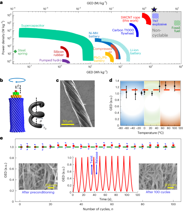
We found the Meijo eDIPS SWCNTs, which were used in our study, to be highly crystalline, and the amount of disordered carbon was very low, as evident from its high G/D ratio of over 100 in the Raman spectrum shown in Supplementary Fig. 4. SWCNT ropes have been prepared by three methods, namely the yarn method resulting in y-ropes, the roll method yielding r-ropes, and the dispersion method to form d-ropes, and the time sequence of these operations is shown in Supplementary Fig. 2.
In the yarn method for rope preparation, we pulled the longest SWCNT strand from the nanotube agglomerate using tweezers, similar to drawing a thread from a silk cocoon. The samples were weighed and deposited onto Teflon sheets. We further densified the sample by adding a few drops of acetone to each SWCNT strand, which penetrated the intertube and interyarn spaces by capillary action. The elongated sample was subsequently twisted several times manually, resulting in what we call a y-rope.
In the roll method, we first dropped <1 ml of acetone, ethanol or water onto 5–10 mg of SWCNT agglomerate. The film was then sandwiched between Teflon sheets and densified by rolling it normal to the SWCNT direction using a roller that applied mechanical pressure. A thin layer was peeled off from the densified SWCNT sheet using Scotch tape. This layer was cut into thin strips along the direction of the SWCNTs and immersed in toluene. The toluene-soaked strips were individually twisted by hand to form what we call an r-rope.
In the dispersion method, also known as buckypaper, we typically dispersed 1 mg of the SWCNT agglomerate in 50 ml of a solvent, such as acetone, toluene or H2O2, and sonicated the suspension. The resulting SWCNT dispersion was filtered and dried at 80 °C to form buckypaper. Similar to the roll method, a thin layer of this buckypaper was peeled off using Scotch tape, cut into strips and immersed in toluene. The toluene-soaked strips were individually twisted manually to form what we call the d-rope.
These fabrication techniques allowed the formation of SWCNT ropes with the desired diameters and lengths to be tested for nanomechanical energy storage using the equipment shown in Fig. 2a. Independent of the fabrication technique, we found that the densification step is crucial for enhancing the load-bearing capacity of the ropes by improving the inter-SWCNT and interyarn load-transfer capabilities34,35.
Modification of SWCNT ropes
The as-obtained SWCNTs ropes were further strengthened by various modification processes, including the deposition of carbon or sulfur or by forming nanocomposites containing TPU or polystyrene (PSS, PSL), followed by microwave irradiation.
To deposit carbon onto the ropes, SWCNT rope samples were placed 25 mm from the carbon rod of a JEOL JEC-530 auto carbon coater equipped with a physical vapour deposition capability. The rod was mounted in a vacuum system between two terminals to provide a high electric current. The deposition of thin carbon films during multiple 10 s cycles, during which the rod was heated to the evaporation temperature of carbon, yielded samples of what we call y-rope (C).
To deposit sulfur, 1 μl of an S/CS2 solution (0.05 or 0.5 mg ml−1) was placed in a glass tube and then the CS2 was completely evaporated. Samples of y-rope (C) were placed in the sulfur-containing glass tube, which was sealed at <1 Pa. Sulfur vapour was then deposited for 1 h under low pressure and at a temperature of 300 °C to form what we call the y-rope (C+S).
To modify SWCNT ropes by TPU, we typically added 100 μl of a TPU/acetone solution (0.54 mg ml−1) to the longest SWCNT strands extracted from SWCNT agglomerates. The elongated samples were subsequently twisted manually several times to form ropes during the yarning. Here, it is worth noticing that during all these modification processes, the alignment of the SWCNTs changed significantly (Fig. 5a and Supplementary Figs. 20 and 21). The initial twist angle (α) of the prepared rope samples was α = 14° ± 4° (Supplementary Fig. 24). Within the s.d. range, the initial twist angle of the prepared samples of comparable dimensions had no significant effect on the overall GED because the rope samples were twisted with a motor in the direction of their initial twist. The resulting samples were maintained under vacuum at 180 °C for 1 h. These ropes were sealed under vacuum (0.06–0.4 Pa) in individual glass tubes, followed by microwave irradiation (200 W) for 5 s, to form SWCNT–TPU nanocomposite ropes called y-ropes (TPU). Although temperature measurement during this irradiation process is difficult, the employed thermocouple must be precisely located near the rope sample. Visual monitoring showed extraneous light which may be due to plasma discharge resulting in a temperature sufficiently higher than the glass-transition temperature of the polymers. PSS- and PSL-based nanocomposite y-ropes (PSS) and y-ropes (PSL) were prepared in a similar way, using PSS/toluene or PSL/toluene solutions (1 mg ml−1). The typical rope diameters ranged from 30 to 100 μm, and the rope lengths were 20–30 mm. A PVA-based nanocomposite y-rope (PVA) was prepared using an aqueous solution with the same concentration as the TPU/acetone solution (0.54 mg ml−1). PVA powder was dissolved in hot water to form an aqueous solution, out of which 2 μl μg−1 was added to the longest SWCNT strands, twisted and dried in a vacuum oven at 100 °C to prepare y-rope (PVA).
Dynamic measurement of the GED
We measured the energy storage in the SWCNT ropes under torsional strain using a Shimadzu automated testing instrument (EZ Test, EZ-LX) with a maximum load capacity of 500 N, a maximum stroke of 920 mm and a stretching test speed ranging from 0.001 to 1,000 mm min−1. To test the sample performance while twisting, the instrument was equipped with eye hooks with a 0.5 mm opening, to which rope samples were mounted firmly using a cyanoacrylate-based adhesive. This adhesive penetrated the interior of the rope, ensuring that all SWCNTs were gripped directly, and no pullout occurred during the load/unload cycles. The tensile force F resulting from twisting an SWCNT rope of initial length L0 and mass m was recorded using a Trapezium X data logger.
In parallel, we measured the torque T resulting from twisting the SWCNT rope with a minute analogue torque gauge connected to the lower eye-hook and viewed it using a high-speed camera. The torque gauge was monitored using ultrahigh-speed/high-accuracy laser displacement LK-G5000 series LK-Navigator 2 configuration software (Keyence). The experimental set-up, including the measurement instrument, imaging equipment and mounted SWCNT rope sample, is shown in Fig. 2a. During the measurements, we performed a careful analysis of the observed values of F and T, which were subject to systematic instrument and measurement errors caused by possible slippage between the rope and the mounting eye-hook, and found no significant errors in our data. The rope sample length used in this study was between 20 and 30 mm and the hook-to-hook length was fixed at 5 mm. Notably, the experiments indicated a dependence of the torque on the rope sample length (Supplementary Fig. 23). With the increasing length of the SWCNT-based ropes, their torque, and hence the GED, decreased, which may be associated with macroscopic defects in the SWCNT ropes created during the fabrication processes that deteriorated the mechanical properties of the resulting rope samples.
Our experimental set-up allows us to measure the effective force constant ks = F/ΔL of a given rope, where ΔL = L − L0 is the change from the initial rope length L0. Analogously, we define and measure the effective torque constant of the rope kt = 2TL/εD. Assuming that the values of ks and kt do not change while twisting the rope, we can evaluate GED using the following expression:
$${mathrm{GED}}=1/2[{k}_{mathrm{s}}Delta {L}^{2}+{k}_{mathrm{t}}{varepsilon }^{2}]/m$$
(1)
However, stress relaxation occurs during quasi-static measurements of force and torque, modifying the values of the force and torque constants. As an alternative for the anharmonic regime, we may assume that the force and the torque remain nearly constant between successive turns n − 1 and n. In this case, we estimate the GED using
$${mathrm{GED}}approxmathop{sum }limits_{1}^{n}[{F}_{n}Delta {L}_{n}+Delta varphi {T}_{n}]/m$$
(2)
where n is the number of full turns that increase the total twist angle by Δφ = 2π in radians. Fn is the force and Tn is the torque after n turns and ΔLn = Ln − Ln−1 is the length change between turns n − 1 and n.
However, because both Fn and Tn change continuously, this assumption has a limited value. To compensate for the errors introduced by finite sampling, we replace the summation in equation (2) with integration and obtain:
$${mathrm{GED}}=left[int F(varphi )({mathrm{d}}L/{mathrm{d}}varphi )delta varphi +int T(varphi )delta varphiright]/m$$
(3)
To perform what we call a dynamic measurement, we connected the load cell to a motor rotating at a constant angular velocity and continuously acquired the values of the tensile force F(φ) and torque Τ(φ) which depend only on the twist angle φ. The integrals extend over the entire range of twist angles φ from zero to their maximum. In our measurement, dL/dφ almost vanishes as the distance between the eyes of the hooks remains the same. In this case, the torque mostly contributes to the GED. Of the three approaches, the one described by equation (3) provides the most accurate estimate of the GED value for a twisted rope. Here, the twist speed had a significant effect on the resulting GED; under comparable conditions, the GED for y-rope was ∼35% higher at 110 rpm compared with that at 10 rpm (Supplementary Fig. 25). This may be attributed to the structural relaxation effect of the SWCNT strands present on the ropes. For a slower rpm, the SWCNT bundles have a sufficiently large time to attain structural relaxation, whereas at a higher rpm, the system does not have sufficient relaxation time, resulting in a 35% enhancement in energy storage. Therefore, all experiments were performed at a twisting speed of 110 rpm, which is the maximum speed at which the rotation number could be counted by lab-made motor equipment and by visual observation.
- SEO Powered Content & PR Distribution. Get Amplified Today.
- PlatoData.Network Vertical Generative Ai. Empower Yourself. Access Here.
- PlatoAiStream. Web3 Intelligence. Knowledge Amplified. Access Here.
- PlatoESG. Carbon, CleanTech, Energy, Environment, Solar, Waste Management. Access Here.
- PlatoHealth. Biotech and Clinical Trials Intelligence. Access Here.
- Source: https://www.nature.com/articles/s41565-024-01645-x
- :has
- :is
- :not
- :where
- ][p
- 000
- 001
- 05
- 1
- 10
- 100
- 101
- 110
- 180
- 2%
- 20
- 200
- 25
- 30
- 300
- 32
- 33
- 34
- 35%
- 4
- 5
- 50
- 500
- 54
- 80
- a
- accelerating
- accurate
- acquired
- Action
- added
- adding
- After
- alignment
- All
- allowed
- allows
- almost
- along
- Alpha
- also
- alternative
- Although
- amount
- an
- analogue
- analysis
- Analytical
- Anchor
- and
- angle
- Angular
- applied
- approaches
- AS
- Assembly
- associated
- assume
- assumption
- At
- attach
- attain
- auto
- Automated
- average
- Axis
- b
- BASF
- BE
- because
- been
- between
- bond
- both
- bundles
- by
- call
- called
- camera
- CAN
- capability
- Capacity
- carbon
- careful
- Carl
- carried
- case
- caused
- cell
- cellular
- Center
- change
- changed
- Changes
- chemical
- click
- comparable
- compared
- compensate
- completely
- concentration
- conditions
- Configuration
- connected
- constant
- containing
- continuously
- contributes
- CORPORATION
- could
- counted
- created
- crucial
- cs
- Current
- Cut
- cycles
- data
- decreased
- define
- depend
- dependence
- deposit
- deposited
- described
- desired
- Determine
- different
- difficult
- digital
- dimensions
- direction
- directly
- dispersed
- Dispersion
- displacement
- distance
- do
- does
- drawing
- dropped
- Drops
- due
- during
- dynamic
- each
- effect
- Effective
- Electric
- employed
- energy
- enhancement
- enhancing
- ensuring
- Entire
- equation
- equipment
- equipped
- erc
- Errors
- estimate
- Ether (ETH)
- evaluate
- evident
- experimental
- experiments
- expression
- extend
- eye
- Eyes
- fabrics
- Failure
- few
- Fig
- Figure
- Film
- films
- filter
- finite
- firmly
- First
- fixed
- followed
- following
- For
- Force
- form
- formation
- forming
- found
- from
- full
- function
- further
- gauge
- giant
- given
- glass
- grade
- Green
- had
- hand
- Have
- helped
- hence
- here
- High
- higher
- highly
- hitachi
- Hooks
- HOT
- HTTPS
- Identification
- images
- Imaging
- immersed
- improving
- in
- incident
- Including
- Increase
- increasing
- independent
- indicated
- individual
- Individually
- initial
- installed
- instrument
- integration
- interior
- into
- introduced
- IT
- ITS
- Japan
- known
- large
- laser
- layer
- Length
- Lens
- light
- Limited
- LINK
- load
- located
- Long
- longest
- Low
- lower
- maintained
- manually
- Mass
- material
- maximum
- May..
- measure
- measured
- measurement
- measurements
- measuring
- mechanical
- method
- methods
- Microscope
- minute
- ML
- modify
- molecular
- monitored
- monitoring
- most
- mostly
- Motor
- multiple
- must
- name
- namely
- nano
- nanotechnology
- Nature
- Near
- nearly
- no
- normal
- notably
- number
- objective
- observation
- observed
- obtain
- obtained
- occurred
- of
- off
- on
- ONE
- only
- onto
- opening
- operated
- Operations
- optical
- or
- our
- out
- over
- overall
- Parallel
- perform
- performance
- performed
- physical
- placed
- Plasma
- plato
- Plato Data Intelligence
- PlatoData
- Polymers
- possible
- precisely
- preparation
- Prepare
- prepared
- present
- pressure
- PROC
- process
- processes
- procured
- Produced
- produces
- Product
- properties
- provide
- provides
- PSL
- purchased
- pure
- quality
- R
- Radiation
- range
- ranging
- ratio
- received
- recorded
- reference
- regime
- relaxation
- remain
- remains
- replace
- resulting
- Roll
- Rolling
- s
- same
- sample
- SCI
- SEM
- seo
- Sequence
- Series
- several
- sheet
- sheets
- showed
- shown
- significant
- significantly
- Silicon
- silk
- similar
- slippage
- slower
- Software
- solution
- Solutions
- spaces
- Spectroscopy
- Spectrum
- speed
- Step
- storage
- Strands
- strengthened
- stress
- structural
- Study
- subject
- Subsequently
- such
- sufficient
- Super
- Surface
- suspension
- system
- tape
- technique
- techniques
- Technologies
- terminals
- test
- tested
- Testing
- text
- than
- that
- The
- their
- then
- therefore
- These
- thin
- this
- three
- time
- times
- to
- Total
- trade
- turns
- twist
- twisted
- two
- typical
- typically
- under
- units
- us
- USA
- used
- using
- Vacuum
- value
- Values
- various
- VeloCity
- very
- viewed
- visual
- Voltage
- W
- was
- Water
- Way..
- we
- weight
- were
- What
- whereas
- which
- while
- with
- within
- worth
- woven
- X
- x-ray
- yielded
- yielding
- zephyrnet
- zero