Much of the recent Keysight EDA 2024 announcement focuses on high-speed digital (HSD) and RF EDA features for Advanced Design System (ADS) and SystemVue users, including RF System Explorer, DPD Explorer (for digital pre-distortion), and design elements for 5G NTN, DVB-S2X, and satcom phased array applications. Two important new features in the Keysight EDA 2024 suite may prove crucial in EDA workflows for chiplets and PDKs (process design kits).
A quick introduction to chiplet interconnects
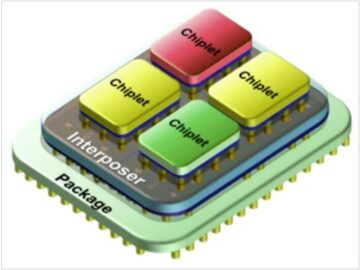
Chiplets are the latest incarnation of modular chip design tracing back through multi-chip module (MCM), system-in-package (SiP), package-on-package (PoP), and others, targeting improved cost-effective design, performance, yield, power efficiency, and thermal management. Chiplets decompose what would otherwise be a complex SoC, with an expensive and maybe unrealizable single-die solution, into smaller pieces designed and tested independently and then packaged together. Chip designers can grab chiplets from different process nodes in a heterogeneous approach – say, putting a 3nm digital logic chiplet alongside a 28nm mixed-signal chiplet.
Until recently, there has been no specification for die-to-die (D2D) interconnects, leaving chiplet designers with two significant challenges. First is the speed of today’s interconnects, often with gigabit clocks, where the bit error rate (BER) starts creeping up enough to affect performance. Second is the difficulty of modeling and simulating interconnects in digital EDA tools, usually in a do-it-yourself approach, trying to match precise time-domain measurements of eye patterns from high-speed oscilloscopes.
UCIe (Universal Chiplet Interconnect Express) fills the gap for D2D interconnects. It defines three layers: a PHY layer with data paths on physical bumps grouped into lanes by signal exit ordering; a D2D adapter coordinating link states, retries, power management, and more; and a protocol layer building on CXL and PCIe specifications. The Standard Package (2D) drives low-cost, long-reach (up to 25mm) interconnects. Advanced Package (2.5D) variants optimize performance on short-reach (less than 2mm) interconnects with tighter bump pitch, enabling improved BER at higher transfer rates. Bump maps and signal exit routing, combined with scalable diagonal bump pitch requirements, ensure that a UCIe-compliant chiplet places on a substrate with controlled interface characteristics, making interoperable connections possible.

A shift left with Chiplet PHY Designer for UCIe
Keysight EDA teams have been working on modeling and simulating HSD interfaces aligned with industry specifications for some time. Their first major product release was ADS Memory Designer with an IBIS-AMI modeler for DDR5/LPDDR5/GDDR7 memory interfaces with statistical and single-ended bus bit-by-bit simulations. Its rigorous and genuine JEDEC compliance testing handles over 100 test IDs with the same test algorithm found in the Keysight Infinium oscilloscope family.
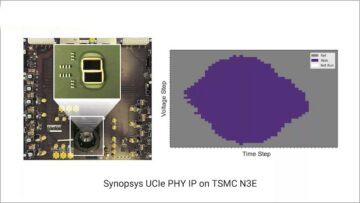
According to Hee-Soo Lee, DDR/SerDes Product Owner and HSD Segment Lead at Keysight, the HSD R&D squad leveraged four years of effort developing Memory Designer in the creation of Chiplet PHY Designer, the industry’s first chiplet interconnect simulation tool ready for introduction as part of ADS 2024 Update 1.0 in the Keysight EDA 2024 suite. “We saw an opportunity to speed up designs using chiplets by simulating a chiplet subsystem, from one D2D PHY through interconnect channels to another D2D PHY, much earlier in the cycle,” says Lee. “Chiplet PHY Designer precisely computes a voltage transfer function (VTF) to ensure specification compliance and analyzes system BER down to 1e-27 or 1e-32 levels.” Chiplet PHY Designer can also measure eye height, eye width, skew, mask margin, and BER contour.

Keysight teams adapted the single-ended bus simulation technology to deal with the single-ended signaling and forwarded clocking used in UCIe. They then incorporated the UCIe signal naming convention and connection rules for handling smart wiring in the schematic. “After placing two dies along with interconnect channels, we can now tell Chiplet PHY Designer to make the automated wiring connections between chiplet components, and the design is ready for simulation right away,” continues Lee. The upcoming November 2023 release of Chiplet PHY Designer puts Keysight ahead of competing EDA environments for chiplet design. Interestingly, Lee hints support for Bunch of Wires (BoW) and Advanced Interface Bus (AIB) is coming in future releases.
Adapt existing PDK models to new process specifications
Creating accurate and high-quality transistor models can be time-consuming and affect the on-time delivery of PDKs. “In the traditional modeling approach, extracting a transistor model card from mass measurement data takes at least several days, often weeks,” says Ma Long, Manager of Device Modeling and Characterization at Keysight.
Keysight IC-CAP now incorporates a new product for model recentering, where models from prior processes are adjusted using figure-of-merits (FOMs) on a new process. “The biggest challenge is addressing the trend plots in real-time, simulating data points for different geometries and temperatures,” says Long. “From threshold voltage, cutoff frequency, and other FOMs, modeling engineers can modify an existing model to new specifications and save 70% compared to traditional step-by-step model extraction.”

Earlier model quality check reduces later iterations
Keysight has a full-featured model quality assurance (QA) tool, MQA, used for final SPICE model library sign-off and documentation. A newly developed light version of MQA, QA Express, is now integrated into Keysight Model Builder (MBP), allowing modeling engineers to apply a quick model QA check during parameter extraction.
Binning model QA is complicated and can also take days or weeks, and issues showing up late in the process can send teams back to the beginning. “QA Express gives easy-to-use, quick results providing a high-confidence check,” Long continues. A faster result is beneficial when simulators toss warnings over parameter effective ranges or bin discontinuity is detected. QA Express enables modeling engineers to find QA issues earlier with one-click ease.

Learn more at the Keysight EDA 2024 product launch event
Keysight has packed many new capabilities into the Keysight EDA 2024 release. For a brief introduction to trends in the EDA market driving these improvements, watch the video featuring Keysight EDA VP and GM Niels Faché below.
[embedded content]
To help current and future users understand the latest enhancements in Keysight EDA 2024, including workflows for chiplets and PDKs, Keysight is hosting an online product introduction event on October 10th and 11th for various time zones.
Registration page:
Keysight EDA 2024 Product Launch Event
Press release for Keysight EDA 2024:
Share this post via:
- SEO Powered Content & PR Distribution. Get Amplified Today.
- PlatoData.Network Vertical Generative Ai. Empower Yourself. Access Here.
- PlatoAiStream. Web3 Intelligence. Knowledge Amplified. Access Here.
- PlatoESG. Carbon, CleanTech, Energy, Environment, Solar, Waste Management. Access Here.
- PlatoHealth. Biotech and Clinical Trials Intelligence. Access Here.
- Source: https://semiwiki.com/eda/keysight-eda/336039-keysight-eda-2024-delivers-shift-left-for-chiplet-and-pdk-workflows/
- :has
- :is
- :where
- $UP
- 1
- 100
- 2023
- 2024
- 2D
- 5G
- a
- About
- accurate
- adapted
- addressing
- Adjusted
- Ads
- advanced
- affect
- ahead
- algorithm
- aligned
- Allowing
- along
- alongside
- also
- an
- analyzes
- and
- Announcement
- Another
- applications
- Apply
- approach
- ARE
- Array
- AS
- assurance
- At
- Automated
- away
- back
- BE
- been
- Beginning
- below
- beneficial
- between
- Biggest
- BIN
- Bit
- builder
- Building
- Bunch
- bus
- by
- CAN
- cap
- capabilities
- card
- challenge
- challenges
- channels
- characteristics
- check
- chip
- Clocks
- combined
- coming
- compared
- competing
- complex
- compliance
- complicated
- components
- connection
- Connections
- content
- continues
- controlled
- Convention
- coordinating
- cost-effective
- creation
- crucial
- Current
- cycle
- cycles
- data
- data points
- Days
- deal
- Defines
- delivers
- delivery
- Design
- designed
- Designer
- designers
- designs
- detected
- developed
- developing
- device
- different
- Difficulty
- digital
- documentation
- down
- drives
- driving
- during
- Earlier
- ease
- easy-to-use
- Effective
- efficiency
- effort
- elements
- embedded
- enables
- enabling
- Engineering
- Engineers
- enhancements
- enough
- ensure
- environments
- error
- Event
- existing
- Exit
- expensive
- explorer
- express
- extraction
- eye
- family
- faster
- Features
- Featuring
- fills
- final
- Find
- First
- focuses
- For
- found
- four
- Frequency
- from
- function
- future
- gap
- genuine
- gives
- GM
- grab
- Handles
- Handling
- Have
- height
- help
- high-quality
- higher
- hints
- hosting
- HTML
- HTTPS
- ids
- important
- improved
- improvements
- in
- Including
- Incorporated
- incorporates
- Increase
- independently
- industry
- industry’s
- integrated
- interconnects
- Interface
- interfaces
- interoperable
- into
- Introduction
- issues
- IT
- ITS
- Late
- later
- latest
- launch
- layer
- layers
- lead
- least
- leaving
- Lee
- left
- less
- levels
- leveraged
- Library
- light
- LINK
- logic
- Long
- low-cost
- major
- make
- Making
- management
- manager
- many
- Maps
- Margin
- Market
- mask
- Mass
- Match
- max-width
- May..
- maybe
- measure
- measurement
- measurements
- Memory
- model
- modeling
- models
- modify
- modular
- module
- more
- much
- naming
- New
- New Features
- new product
- newly
- no
- nodes
- November
- now
- october
- of
- often
- on
- ONE
- online
- Opportunity
- Optimize
- or
- Other
- Others
- otherwise
- over
- owner
- package
- packaged
- packages
- packed
- page
- parameter
- part
- patterns
- performance
- Phased
- physical
- pieces
- Pitch
- Places
- placing
- plato
- Plato Data Intelligence
- PlatoData
- points
- pop
- possible
- Post
- power
- precise
- precisely
- Prior
- process
- processes
- Product
- product launch
- protocol
- Prove
- providing
- Puts
- Putting
- Q&A
- quality
- Quick
- R&D
- Rate
- Rates
- ready
- real-time
- recent
- recently
- reduces
- release
- Releases
- Requirements
- result
- Results
- right
- rigorous
- routing
- rules
- same
- Save
- saw
- say
- says
- scalable
- Second
- segment
- send
- several
- shift
- showing
- Signal
- significant
- simulation
- simulations
- skew
- smaller
- smart
- Software
- solution
- some
- specification
- specifications
- speed
- spice
- standard
- starts
- States
- statistical
- suite
- support
- system
- Take
- takes
- Talks
- targeting
- teams
- Technology
- tell
- test
- tested
- Testing
- than
- that
- The
- their
- then
- There.
- thermal
- These
- they
- this
- three
- threshold
- Through
- tighter
- time
- time-consuming
- to
- today’s
- together
- tool
- tools
- toss
- Tracing
- traditional
- transfer
- Trend
- Trends
- trying
- two
- understand
- upcoming
- Update
- used
- users
- using
- usually
- various
- version
- via
- Video
- Voltage
- vp
- was
- Watch
- we
- Weeks
- What
- when
- with
- workflows
- working
- would
- years
- Yield
- youtube
- zephyrnet
- zones