In the continuing series on the PCIe / PCI Express bus, we’ve found out what it is, terminology, and bandwidth. Now let’s look at how things are connected to the bus.
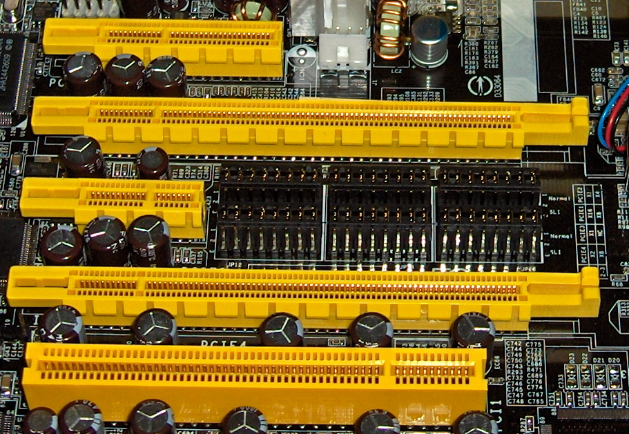
The number of lanes provided by the CPU is mapped into a number of physical connectors (and at times to chips for peripherals). Let’s look at the standard connectors.
Seen above are some of the PCIe connectors: x4, x16, x1, and another x16 (and an older PCI slot which is not compatible). There is a x8 connector not shown.
Now you might think that a x4 sized connector would have 4 PCIe lanes. Often this is true, with x1 having one lane, x16 having 16 lanes. BUT THIS IS NOT ALWAYS THE CASE.

Famously in some older Intel i7 motherboards, one x16 slot (top) would have 16 lanes while the other slot had four or maybe 8 lanes (bottom) as the CPU did not have enough for all the peripherals. So using two x16 graphics cards would not give the optimal bandwidth as one card is throttled by having fewer lanes.
The card and motherboard negotiate the available PCIe lanes and if all is programmed correctly, devices usually afforded multiple PCIe lanes can work with fewer, albeit at reduced bandwidth.

The connectors allow for smaller cards to fit larger slots. In rarer cases, a smaller slot may physically accept a larger card, as above (compare this to the x1 connectors above which have a closed footprint not allowing larger cards as there is no slot to accommodate it.
If you are looking at a computer with limited resources, such as the new Raspberry Pi 5, keep in mind how the PCIe connection might be made. Installing a x1 connector will limit to x1 cards unless an open back connector is used.
And always be aware of the bandwidth available vs. what the add-on card might want. If your add-on is running slow, it’s likely due to limited PCIe lanes.
Next: How to extend and expand PCIe connections.
- SEO Powered Content & PR Distribution. Get Amplified Today.
- PlatoData.Network Vertical Generative Ai. Empower Yourself. Access Here.
- PlatoAiStream. Web3 Intelligence. Knowledge Amplified. Access Here.
- PlatoESG. Carbon, CleanTech, Energy, Environment, Solar, Waste Management. Access Here.
- PlatoHealth. Biotech and Clinical Trials Intelligence. Access Here.
- Source: https://blog.adafruit.com/2023/10/04/pcie-pci-express-connections/
- :is
- :not
- 16
- 321
- 8
- a
- above
- Accept
- accommodate
- Add-on
- afforded
- All
- allow
- Allowing
- always
- an
- and
- Another
- ARE
- AS
- At
- available
- aware
- back
- Bandwidth
- BE
- Bottom
- bus
- but
- by
- CAN
- card
- Cards
- case
- cases
- Chips
- closed
- compare
- compatible
- computer
- connected
- connection
- Connections
- continuing
- correctly
- CPU
- Devices
- DID
- due
- enough
- Expand
- express
- extend
- fewer
- fit
- Footprint
- For
- found
- four
- Give
- graphics
- had
- Have
- having
- High
- How
- How To
- HTTPS
- if
- in
- installing
- Intel
- into
- IT
- Keep
- Lane
- larger
- likely
- LIMIT
- Limited
- Look
- looking
- made
- max-width
- May..
- maybe
- might
- mind
- multiple
- New
- no
- now
- number
- of
- older
- on
- ONE
- open
- optimal
- or
- Other
- out
- peripherals
- physical
- Physically
- plato
- Plato Data Intelligence
- PlatoData
- programmed
- provided
- Reduced
- Resources
- running
- Series
- shown
- sized
- slot
- slots
- slow
- smaller
- So
- some
- standard
- such
- that
- The
- There.
- things
- Think
- this
- times
- to
- top
- two
- used
- using
- usually
- vs
- want
- What
- which
- while
- will
- with
- Work
- would
- x8
- you
- Your
- zephyrnet