Using the Basic graphics control of STONE serial screen, you can draw lines, triangles, polygons, rectangles, squares, circles, arcs, fill colors, cut and paste, and so on.
The design of an early learning machine using the serial touch screen STVI056WT-01, to identify shapes by looking at the pictures, to recognize words according to colors, and to design an entertainment format to determine the correct errors, score or pass the level, so that children can learn to recognize colors, understand basic shapes and learn the corresponding words in a relaxed and playful way.
The official video presentation does not give the actual effect of the Basic graphics control, so this demo will supplement it. The instructions for drawing are transmitted through the communication between the arduino control board and the STONE serial screen.
In addition, this note does not include the complete functional content of the Basic graphics control, only the functions used in the use of the elaboration, the recorded are tested on the machine OK, you can directly download the demo run.
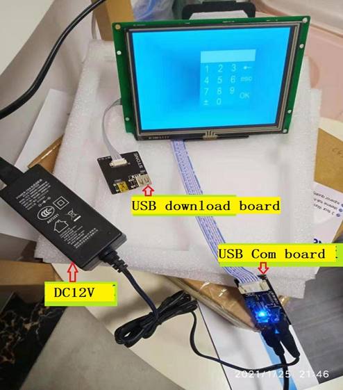
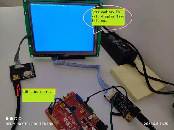
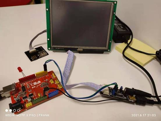
The hardware environment for the demo is shown in Figure 1, Figure 2 and Figure 3.
STONE officially comes with 2 boards, among which, the square one is a USB download board and the long one is a USB to serial communication board (and DC12V power supply for the serial screen).
(Figure 1: Communication and power connection of STONE serial screen) (Figure 2: Connection diagram for downloading Basic Graphics control files from STONE screen)
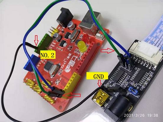
(Figure 3: TX, RX, GND connection between STONE serial screen communication board and arduino development board)
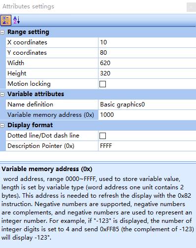
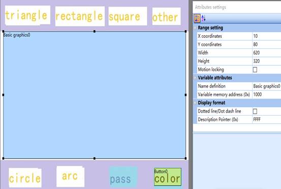
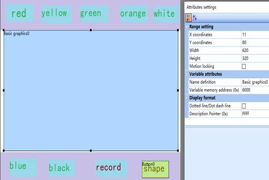
(Figure 4: Basic graphics control drawing area and variable address and other parameter settings)
After selecting the Basicgraphics control in the STONE TOOLBox(GUI Design software) menu Variable Configuration (D), and setting the drawing area and variable address parameters, the 0x82 instruction is used to write to the set Variable memory address (0x1000 is set here) After setting the drawing area and variable address parameters, the 0x82 instruction is used to write CMD + Data_pack_Num_Max + Data to the set Variable memory address (0x1000 in this case) to complete the implementation of the drawing functions. The specific function code is shown in Figure 6, where there is a line drawing instruction 0x0002, using the following example.
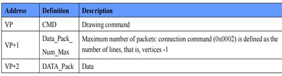
(Figure 5: Basic graphics control data command format)
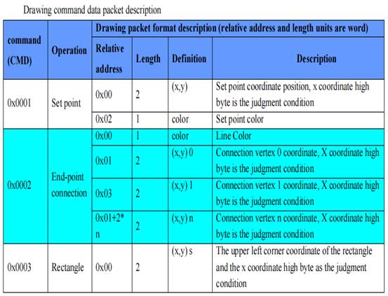
(Figure 6: Illustration of drawing line and rectangle commands for Basic graphic control)
Line drawing instruction 0x0002, example of use.
To connect a black line from coordinates (340, 200) to coordinates (585, 200), the instruction is
A5 5A 11 82 10 00 00 02 00 01 00 00 01 54 00 C8 02 49 00 C8
Draw three black lines closed into a triangle with three vertices at coordinates (200, 200), (300, 200), (250, 100), and the instruction is
A5 5A 19 82 10 00 00 02 00 03 00 00 00 00 C8 00 C8 01 2C 00 C8 00 FA 00 64 00 C8 00 C8
The above 0x1000 is the variable address of Basic graphics control, 0x0002 is the instruction code, 0x0001 and 0x0003 are 1 line and 3 lines respectively, 0x0000 is the color code, the value 0000 is black and the value ffff is bright white. Other instant XY coordinates of each point.
Example of drawing a rectangle.
Rectangle upper left vertex coordinates (340, 237), lower right vertex coordinates (585, 340) color black, the command is
A5 5A 11 82 10 00 00 03 00 01 01 54 00 ED 02 49 01 54 00 00
Simultaneously draw two rectangles (340, 237) – (585, 340), (324, 221) – (601, 356), the command is
A5 5A 1B 82 10 00 00 03 00 02 01 54 00 ED 02 49 01 54 00 00 01 44 00 DD 02 59 01 64 FF FF
The above 0x1000 is the variable address of Basic graphics control, 0x0003 is the rectangle command code, 0x0001, 0x0002 are 1 rectangle, 2 rectangles, 0x0000, 0xffff is the color code, the value of 0000 is black, the value of fffff is bright white. The others are the XY coordinates of the top left vertex and bottom right vertex of each rectangle.
(Figure 7: Rectangle fill and draw circle commands for Basic graphics control)
Rectangle fill example.
The black rectangle fill (470, 200) ~ (550 ,255) command is
A5 5A 11 82 10 00 00 04 00 01 01 D6 00 C8 02 26 00 FF 00 00 00
Example of drawing a circle.
The center of the circle (470, 200), R = 50 black, the instruction is
A5 5A 0F 82 10 00 00 05 00 01 01 D6 00 C8 00 32 00 00
To draw two circles at the same time, center A (470, 200) R=50 and center B (256, 200) R=80, both in black, the command is
A5 5A 17 82 10 00 00 05 00 02 01 D6 00 C8 00 32 00 00 01 00 00 C8 00 50 00 00
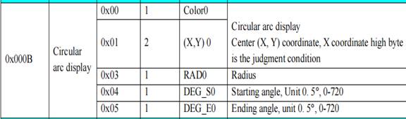
(Figure 8: Arc command for Basic graphics control)
The arc resolution is 0.5 degrees, 360 degrees corresponds to 720, and 0 degrees is in the vertical upward direction.
Arc example.
The upper arc 315 degrees to start – 45 degrees to end, the center of the circle (300, 200) R = 80, black, the command is
A5 5A 13 82 10 00 00 0B 00 01 00 00 01 2C 00 C8 00 50 02 76 00 5A
Regarding colors.
0x0000 is black 0xffff is white 0x00ff is blue 0xf000 is red 0xfd60 is orange
0xff60 is yellow 0x2f60 is green
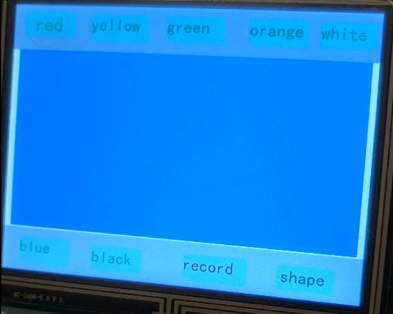
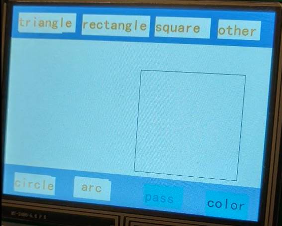
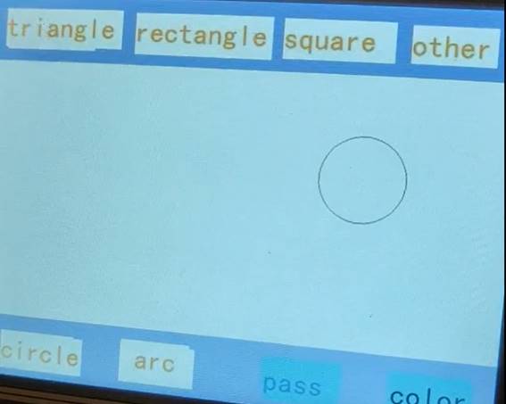
(Figure 9: Basic graphics control shape interface drawing board parameters and addresses)
(Figure 10: Drawing board parameters and addresses of the Basic graphics control color interface)
According to the variable address, the command to fill green color for (10, 80) ~ (630, 400) is
A5 5A 11 82 60 00 00 04 00 01 00 0A 00 50 02 76 01 90 2f 60
Other similarities, see the program code for details.
The code demonstrated in the video is as follows.
/*
frank10
STONE and arduino COMM, the Basic graphics play at program..
Turns on an LED on for one second, then off for one second, repeatedly.The LED tell our that the soft running ok!
The sample has two page.The page1 is shape, the page2 is corlor!
This example code is in the file of frank. 20210625
*/
// Pin 13 has an LED connected on most Arduino boards.
// give it a name:
int led = 13;
int iYePian = 0; //0x0020 for The num of YePian!
//int iGongLu = 0; //0x0180 for The GongLu!
//int iLiuLiang = 0; //0x0160 for The now LiuLiang!
int iJiao = 0; // 0x0260 for The JieJuJiao!
int iGongLuWater = 0; //0x0280 for The Water GongLu! value is 0-50000!
int iLed = 1; //delay time num.
int iLed2 = 1; //delay time num. 50ms do a point.
int iLed3 = 0; //delay time num. 50ms do a point.
int iLed4 = 0; //delay time num. 50ms do a point.
int iCurve0 = 0; //The value of curve0. 50ms do a point.
int iCurve1 = 0; //The value of curve1,. 50ms do a point.
int iFlag0 = 1; // The flag of the curve0 + or -; .1 is up,0 is down.
int iFlag1 = 1; // The flag of the curve1 + or -; .1 is up,0 is down.
int iNum = 0 ; //read in char num.
int iNum2 = 0; //read in char num2 for ShuiDianZhan!
//int iPower = 2; //key statue 0x0009
//int iMode = 2; //key statue 0x000A
int iPowerWater = 2; //key statue 0x0039
// the setup routine runs once when you press reset:
void setup() {
// initialize the digital pin as an output.
pinMode(led, OUTPUT);
Serial.begin(115200); // Open the serial communication function and wait for the serial port to open
while (!Serial) {
; // wait for serial port to connect. Needed for Leonardo only
}
}
// the loop routine runs over and over again forever:
void loop() {
int inChar;
/*——————————————————————————-*/
if (iLed == 800) {
//——- read 0x0039 value———-
Serial.write(0xA5); //”A5″ is 165
Serial.write(0x5A); //”5A” is 90
Serial.write(0x04); //lenght
Serial.write(0x83); // read!
Serial.write(0x00); // address of ShuiDianZhan Power key!
Serial.write(0x39); // address of ShuiDianZhan power key!
Serial.write(0x01); // 0x0039(power key)
//———STONE return value will be “A5 5A 06 83 00 39 01 00 01 “——
}
// Read the information sent by the serial port:
if (Serial.available() > 0) { inChar = Serial.read(); }
/*
save a bak.
because can have a read key and have a work of key.
the program is a HMI that a key of input do a work of peplose.
*/
//————————————————————————————
//—————————-0x0039 key read begin———————————–
if (inChar == 0x39) { iNum2 = 1 ; }
if ((inChar == 0x01)&&(iNum2 == 1)) { iNum2 = 2 ; }
if ((inChar == 0x00)&&(iNum2 == 2)) { iNum2 = 3 ; }
if ((inChar == 0x01)&&(iNum2 == 3)) {
iNum2 = 0 ;
if(iPowerWater != 1){
iPowerWater = 1 ; //power ON!
iJiao = 0 ;
iGongLuWater = 0 ;
}
}
if ((inChar == 0x02)&&(iNum2 == 3)) {
iNum2 = 0 ;
iPowerWater = 2 ; //power OFF!
}
//——————0x0039 key read ok! iPowerWater ok!—————————-
//————————————————————————————
delay(1);
iLed += 1;
iLed2 += 1; // 50ms do a point.
//——————————————————————————————–
//———————————50ms do a point begin————————————–
if (iLed2 == 50) {
iLed2 = 1;
iLed4 += 1; // 50ms do a point.
if(iFlag0 == 1){
iCurve0 += 1; // 50ms do a point.
if(iCurve0 >= 150){
iFlag0 = 0; // The iCurve0 turn down!.
}
}
if(iFlag0 == 0){
iCurve0 -= 1; // 50ms do a point.
if(iCurve0 <= 1){
iFlag0 = 1; // The iCurve0 turn up!.
}
}
if(iFlag1 == 1){
if(iLed4 >= 3){
iCurve1 += 1; // 50ms do a point.
iLed4 = 0;
}
if(iCurve1 >= 50){
iFlag1 = 0; // The iCurve1 turn down!.
}
}
if(iFlag1 == 0){
if(iLed4 >= 3){
iLed4 = 0;
iCurve1 -= 1; // 50ms do a point.
}
if(iCurve1 <= 1){
iFlag1 = 1; // The iCurve1 turn up!.
}
}
Serial.write(0xA5); //”A5″ is 165
Serial.write(0x5A); //”5A” is 90
Serial.write(0x06);
Serial.write(0x84); //write to curve!
Serial.write(0x03); // The curve path,
Serial.write(iCurve0); // N=1,
Serial.write(0x00);
Serial.write(iCurve1);
Serial.write(0x00);
}
//——————————-50ms do the point end—————————————
//——————————————————————————————-
if (iLed == 500) {
digitalWrite(led, HIGH); // turn the LED on (HIGH is the voltage level)
//delay(500); // wait for a second, Range:200-2000
}
if (iLed >= 1000) {
digitalWrite(led, LOW); // turn the LED off by making the voltage LOW
//delay(500); // wait for a second, range:200-2000
iLed = 1;
if( iNum <= 6 ) iNum += 1; //shape turn!
if( iNum == 6 ) iNum = 0; //shape turn!
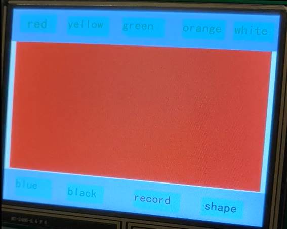
//————————————–The red is begin—————————————–
if( iNum == 1){ // triangle! and red!
Serial.write(0xA5); //”A5″ is 165
Serial.write(0x5A); //”5A” is 90
Serial.write(0x19);
Serial.write(0x82);
Serial.write(0x10); // addressH of Basic graphics
Serial.write(0x00); // addressL of Basic graphics
Serial.write(0x00); // Do line CMD
Serial.write(0x02); // Do line CMD
Serial.write(0x00); // the number of the line
Serial.write(0x03); // The number of the line.
Serial.write(0x00); //colorH black
Serial.write(0x00); //colorL
Serial.write(0x00); // pointX1H
Serial.write(0xc8); // pointX1L
Serial.write(0x00); // pointY1H
Serial.write(0xc8); // pointY1L
Serial.write(0x01); // pointX2H
Serial.write(0x2C); // pointX2L.
Serial.write(0x00); // pointY2H
Serial.write(0xC8); // pointY2L
Serial.write(0x00); // pointX3H
Serial.write(0xFA); // pointX3L
Serial.write(0x00); // pointY3H
Serial.write(0x64); // pointY3L
Serial.write(0x00); // pointX1H
Serial.write(0xc8); // pointX1L
Serial.write(0x00); // pointY1H
Serial.write(0xc8); // pointY1L
//fill—–
Serial.write(0xA5); //”A5″ is 165
Serial.write(0x5A); //”5A” is 90
Serial.write(0x11);
Serial.write(0x82);
Serial.write(0x60); // addressH of Basic graphics page2
Serial.write(0x00); // addressL of Basic graphics pabe2
Serial.write(0x00); // Do Fill rectangle CMD
Serial.write(0x04); // Do Fill rectangle CMD
Serial.write(0x00); // the number of the rectangle
Serial.write(0x01); // The number of the rectangle
Serial.write(0x00); // pointX1H
Serial.write(0x0A); // pointX1L
Serial.write(0x00); // pointY1H
Serial.write(0x50); // pointY1L
Serial.write(0x02); // pointX2H
Serial.write(0x76); // pointX2L.
Serial.write(0x01); // pointY2H
Serial.write(0x90); // pointY2L
Serial.write(0xF0); // Red colorH
Serial.write(0x00); // Red colorL
}
//————————————–The red is end—————————————–
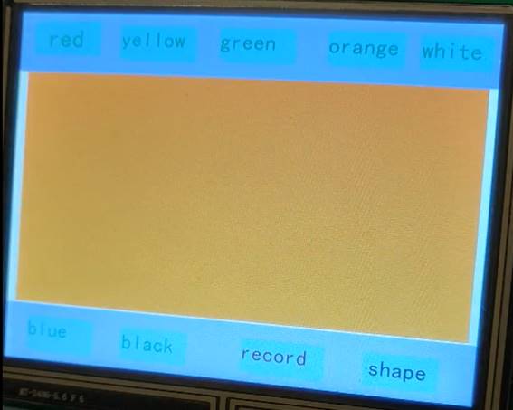
//————————————–The yellow and the arc is begin—————————————–
if( iNum == 2){ // arc! and yellow!
Serial.write(0xA5); //”A5″ is 165
Serial.write(0x5A); //”5A” is 90
Serial.write(0x13);
Serial.write(0x82);
Serial.write(0x10); // addressH of Basic graphics page1
Serial.write(0x00); // addressL of Basic graphics pabe1
Serial.write(0x00); // Do arc CMD
Serial.write(0x0B); // Do arc CMD
Serial.write(0x00); // the number of the arc
Serial.write(0x01); // The number of the arc.
Serial.write(0x00); // colorH black
Serial.write(0x00); // colorL blank
Serial.write(0x01); // centel of circle XH
Serial.write(0x2c); // centel of circle XL
Serial.write(0x00); // centel of circle YH
Serial.write(0xc8); // centel of circle YL
Serial.write(0x00); // RH
Serial.write(0x50); // RL.
Serial.write(0x02); // Angle1H
Serial.write(0x76); // Angle1L
Serial.write(0x00); // Angle2H
Serial.write(0x5A); // Angle2L
//fill—–
Serial.write(0xA5); //”A5″ is 165
Serial.write(0x5A); //”5A” is 90
Serial.write(0x11);
Serial.write(0x82);
Serial.write(0x60); // addressH of Basic graphics page2
Serial.write(0x00); // addressL of Basic graphics pabe2
Serial.write(0x00); // Do Fill rectangle CMD
Serial.write(0x04); // Do Fill rectangle CMD
Serial.write(0x00); // the number of the rectangle
Serial.write(0x01); // The number of the rectangle
Serial.write(0x00); // pointX1H
Serial.write(0x0A); // pointX1L
Serial.write(0x00); // pointY1H
Serial.write(0x50); // pointY1L
Serial.write(0x02); // pointX2H
Serial.write(0x76); // pointX2L.
Serial.write(0x01); // pointY2H
Serial.write(0x90); // pointY2L
Serial.write(0xFF); // Yellow colorH
Serial.write(0x60); // Yellow colorL
}
//————————————–The yellow and the arc is end—————————————–
//————————————–The green and the rectangle is begin—————————————–
if( iNum == 3){ // rectangle! and green!
Serial.write(0xA5); //”A5″ is 165
Serial.write(0x5A); //”5A” is 90
Serial.write(0x11);
Serial.write(0x82);
Serial.write(0x10); // addressH of Basic graphics page1
Serial.write(0x00); // addressL of Basic graphics pabe1
Serial.write(0x00); // Do rectangle CMD
Serial.write(0x03); // Do rectangle CMD
Serial.write(0x00); // the number of the rectangle
Serial.write(0x01); // The number of the rectangle
Serial.write(0x01); // pointX1H
Serial.write(0x54); // pointX1L
Serial.write(0x00); // pointY1H
Serial.write(0xED); // pointY1L
Serial.write(0x02); // pointX2H
Serial.write(0x49); // pointX2L.
Serial.write(0x01); // pointY2H
Serial.write(0x54); // pointY2L
Serial.write(0x00); // colorH black
Serial.write(0x00); // colorL blank
//fill—–
Serial.write(0xA5); //”A5″ is 165
Serial.write(0x5A); //”5A” is 90
Serial.write(0x11);
Serial.write(0x82);
Serial.write(0x60); // addressH of Basic graphics page2
Serial.write(0x00); // addressL of Basic graphics pabe2
Serial.write(0x00); // Do Fill rectangle CMD
Serial.write(0x04); // Do Fill rectangle CMD
Serial.write(0x00); // the number of the rectangle
Serial.write(0x01); // The number of the rectangle
Serial.write(0x00); // pointX1H
Serial.write(0x0A); // pointX1L
Serial.write(0x00); // pointY1H
Serial.write(0x50); // pointY1L
Serial.write(0x02); // pointX2H
Serial.write(0x76); // pointX2L.
Serial.write(0x01); // pointY2H
Serial.write(0x90); // pointY2L
Serial.write(0x2F); // Green colorH
Serial.write(0x60); // Green colorL
}
//————————————–The green and the rectangle is end—————————————–
//————————————–The orange and the square is begin—————————————–
if( iNum == 4){ // square! and orange!
Serial.write(0xA5); //”A5″ is 165
Serial.write(0x5A); //”5A” is 90
Serial.write(0x11);
Serial.write(0x82);
Serial.write(0x10); // addressH of Basic graphics page1
Serial.write(0x00); // addressL of Basic graphics pabe1
Serial.write(0x00); // Do rectangle CMD
Serial.write(0x03); // Do rectangle CMD
Serial.write(0x00); // the number of the rectangle
Serial.write(0x01); // The number of the rectangle
Serial.write(0x01); // pointX1H
Serial.write(0x54); // pointX1L
Serial.write(0x00); // pointY1H
Serial.write(0x91); // pointY1L
Serial.write(0x02); // pointX2H
Serial.write(0x49); // pointX2L.
Serial.write(0x01); // pointY2H
Serial.write(0x86); // pointY2L
Serial.write(0x00); // colorH black
Serial.write(0x00); // colorL blank
//fill—–
Serial.write(0xA5); //”A5″ is 165
Serial.write(0x5A); //”5A” is 90
Serial.write(0x11);
Serial.write(0x82);
Serial.write(0x60); // addressH of Basic graphics page2
Serial.write(0x00); // addressL of Basic graphics pabe2
Serial.write(0x00); // Do Fill rectangle CMD
Serial.write(0x04); // Do Fill rectangle CMD
Serial.write(0x00); // the number of the rectangle
Serial.write(0x01); // The number of the rectangle
Serial.write(0x00); // pointX1H
Serial.write(0x0A); // pointX1L
Serial.write(0x00); // pointY1H
Serial.write(0x50); // pointY1L
Serial.write(0x02); // pointX2H
Serial.write(0x76); // pointX2L.
Serial.write(0x01); // pointY2H
Serial.write(0x90); // pointY2L
Serial.write(0xFD); // orange colorH
Serial.write(0x60); // orange colorL
}
//————————————–The orange and the square is end—————————————–
//————————————–The blue and the circle is begin—————————————–
if( iNum == 5){ // circle! and blue!
Serial.write(0xA5); //”A5″ is 165
Serial.write(0x5A); //”5A” is 90
Serial.write(0x0F);
Serial.write(0x82);
Serial.write(0x10); // addressH of Basic graphics page1
Serial.write(0x00); // addressL of Basic graphics pabe1
Serial.write(0x00); // Do circle CMD
Serial.write(0x05); // Do circle CMD
Serial.write(0x00); // the number of the circle
Serial.write(0x01); // The number of the circle
Serial.write(0x01); // centel of circle XH
Serial.write(0xD6); // centel of circle XL
Serial.write(0x00); // centel of circle YH
Serial.write(0xc8); // centel of circle YL
Serial.write(0x00); // RH
Serial.write(0x32); // RL.
Serial.write(0x00); // colorH black
Serial.write(0x00); // colorL blank
//fill—–
Serial.write(0xA5); //”A5″ is 165
Serial.write(0x5A); //”5A” is 90
Serial.write(0x11);
Serial.write(0x82);
Serial.write(0x60); // addressH of Basic graphics page2
Serial.write(0x00); // addressL of Basic graphics pabe2
Serial.write(0x00); // Do Fill rectangle CMD
Serial.write(0x04); // Do Fill rectangle CMD
Serial.write(0x00); // the number of the rectangle
Serial.write(0x01); // The number of the rectangle
Serial.write(0x00); // pointX1H
Serial.write(0x0A); // pointX1L
Serial.write(0x00); // pointY1H
Serial.write(0x50); // pointY1L
Serial.write(0x02); // pointX2H
Serial.write(0x76); // pointX2L.
Serial.write(0x01); // pointY2H
Serial.write(0x90); // pointY2L
Serial.write(0x00); // blue colorH
Serial.write(0xFF); // blue colorL
}
//————————————–The blue and the circle is end—————————————–
Finally, online debugging.

STONE TOOLBox(GUI Design software) will edit the screen file download, arduino code file upload, connect the power supply, communication, power on to observe the image drawing and color change, to achieve the desired effect.
The code demonstrated in the video is as follows.
(online tuning attempts)
Source: Plato Data Intelligence